What Is 3D Lenticular Printing and How Does It Work?
3D lenticular printing creates an illusion of depth or movement on a flat printed surface. It relies on a transparent plastic sheet with tiny ridges, called lenticules, placed over carefully prepared images. Each ridge directs different image strips toward the viewer’s eyes. As the viewing angle changes, the visible image changes too. It feels almost animated. The printed surface itself remains flat.
To 3D Print Lenticular images successfully, designers must prepare and align the image layers with the lens sheet’s pitch. Small alignment errors can cause ghosting, blurred edges, or an effect that works only from one narrow angle. Viewing distance, lighting, image contrast, and print quality also influence the result. These details matter in practical projects, from promotional cards and packaging to signs that reveal a second image as someone walks past.
The effect has limits. Lenticular printing does not create real, touchable depth, and a dramatic preview may look less convincing under uneven light. A useful guide should explain the image preparation, printing, and alignment process, while also showing where results can go wrong. That caveat is worth keeping. Understanding both the visual trick and its constraints helps readers judge whether lenticular printing suits their project—and what to test before producing a full run.
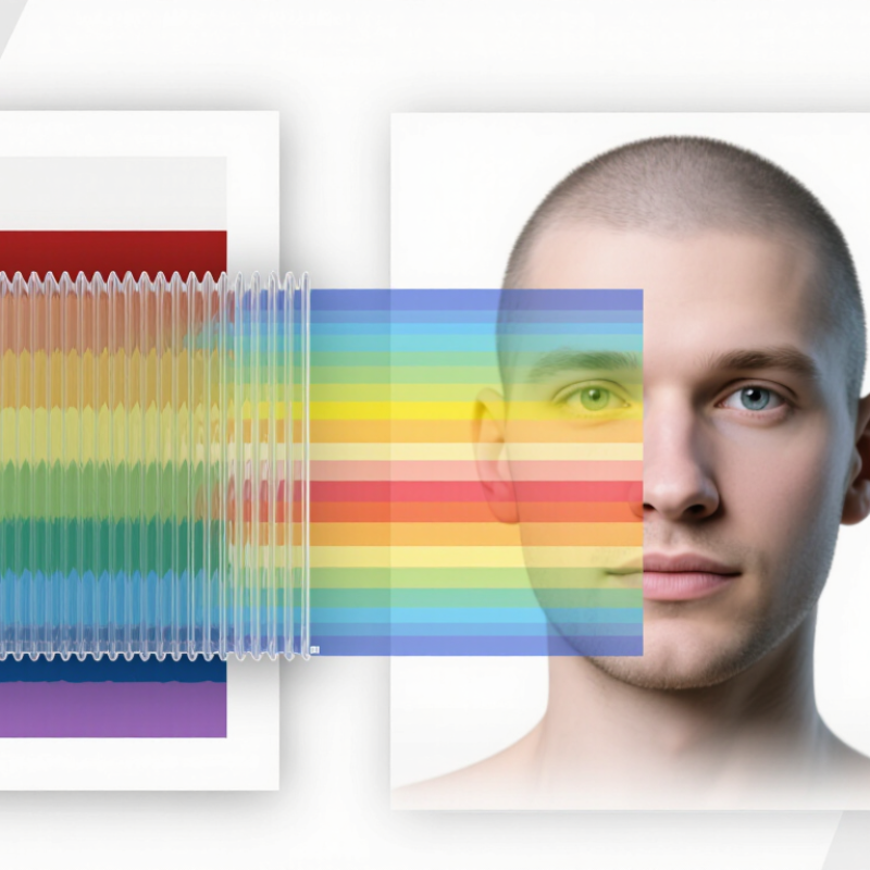
3D Lenticular Printing: Creating Depth from Interlaced Perspective Views
Lenticular printing creates depth by placing several slightly different views beneath a ridged plastic lens sheet. Each lens, or lenticule, directs a narrow strip of the image toward the viewer. As the viewing angle changes, the eye receives a different perspective. The brain reads that shift as depth or motion. The effect is not magic.
Print-industry technical specifications commonly describe lens sheets at 40–100 lenticules per inch (LPI). At 60 LPI, each lenticule is about 0.42 millimeters wide, so image alignment must be precise. The artwork is divided into thin strips, interlaced in sequence, then matched to the lens pitch. A slight mismatch can produce ghosting: two views appear at once, softening the subject’s edges. That is easy to miss on a screen. A useful production check is to tilt a printed sample slowly under ordinary room lighting and confirm that views change cleanly. More views can make transitions smoother, but they also leave fewer printed pixels for each view. This trade-off deserves attention; deeper effects are not always clearer.
Lenticular Lens Pitch: 40 LPI Equals a 0.635 mm Lens Spacing
At 40 LPI, a lenticular sheet carries 40 lens ridges across each inch. NIST’s SP 811 uses the exact conversion of 1 inch to 25.4 mm, so the nominal pitch is 25.4 ÷ 40 = 0.635 mm. That is the center-to-center spacing between adjacent lenticules, not the thickness of the plastic. Tiny spacing, real consequences.
The printed image must be interlaced to match this pitch. Narrow image strips sit beneath each lens, directing different views toward different angles. A small mismatch can show as ghosting, soft edges, or an image that changes too early when tilted. The arithmetic is exact; production is less tidy. Film stretch, printer resolution, viewing distance, and the sheet’s measured pitch can all affect alignment. A nominal 40 LPI sheet may not behave like a perfect 40.000 LPI surface.
For reliable setup, measure the actual sheet and run a small alignment test before printing a full batch. Record the pitch, viewing distance, and observed flip points. ISO 12647-2:2013 provides process-control guidance for offset printing, but it does not prescribe lenticular pitch calibration; that distinction matters. Treat 0.635 mm as a starting specification, then verify the physical sheet and print together.
What Is 3D Lenticular Printing and How Does It Work? — Lenticular Lens Pitch: 40 LPI Equals a 0.635 mm Lens Spacing
| Dimension | Value or specification | Meaning |
| Lens pitch | 40 LPI | LPI means lenticular lenses per inch. The pitch describes the number of lens elements across one inch. |
| Lens spacing at 40 LPI | 0.635 mm (0.025 in) | Calculated as 25.4 mm per inch ÷ 40 lenses per inch. This is the nominal center-to-center spacing of adjacent lens elements. |
| Pitch conversion examples | 60 LPI: 0.423 mm
75 LPI: 0.339 mm
100 LPI: 0.254 mm | Values are calculated using 25.4 mm ÷ LPI and rounded to three decimal places. Higher LPI means more closely spaced lenses. |
| Image preparation | Multiple views are interlaced | Images captured or rendered from different viewpoints are divided into narrow strips and combined into a single interlaced image. |
| Lens-sheet function | Directs different image strips toward different viewing angles | The lenticular surface refracts light so that the viewer sees different strips as the viewing angle changes. |
| Perceived 3D effect | Depends on the view sequence and viewing conditions | Each eye can receive a different viewpoint; the brain uses this binocular disparity as a depth cue. The effect varies with image design, lens alignment, and viewing distance. |
| Alignment requirement | Interlaced image must align with the lens pitch and direction | Misalignment can cause image ghosting, blur, or the wrong view to appear. The exact setup depends on the lens sheet and printing process. |
| Resolution relationship at 40 LPI | At 300 pixels per inch: 7.5 source pixels per lens pitch | Calculated as 300 PPI ÷ 40 LPI. This is a sampling relationship, not a guarantee of print quality; the final result also depends on printer capability and precise calibration. |
LPI is a measure of lens frequency. Lens spacing is the reciprocal of that frequency, converted to the desired unit.
Preparing the View Set: Capture or Render Images from Multiple Angles
For a 3D lenticular print, the view set is a sequence of images showing a subject from slightly different angles. The printer later interlaces these views beneath a lenticular lens, so small inconsistencies can appear as jumps or blur. Keep the camera fixed and rotate the object, or move the camera along a measured arc around a stationary subject. Use even angle steps, and keep the subject’s distance and height consistent. Keep it steady. Lock focus, exposure, and white balance; changing them between shots can create distracting flicker. A plain, evenly lit background helps reveal alignment problems.
For rendered images, create matching virtual cameras and use the same lens, framing, lighting, and render settings for every view. Set the angular range to suit the subject: a small turn may be enough for a product, while a larger range can make a scene feel deeper but may expose empty sides. Check that details do not suddenly disappear between neighboring views. Then arrange the files in exact camera order and inspect a low-cost test print under the intended lens. I would not assume a smooth animation in preview guarantees a smooth print. Lenticular pitch, viewing distance, and alignment all affect the result, so a test may reveal a sequence that needs adjustment.
Interlacing and Printing: Match Image Strips to the Lens Pitch
Interlacing divides each view into narrow strips, then combines them into one image beneath the lenticular sheet. The lens pitch sets the repeating width of that pattern. Match the strip spacing to the measured pitch, not just the nominal label on the stock. A small mismatch can produce doubled edges or a jumpy image.
For example, 40 lenses per inch gives a nominal pitch of 0.635 mm: 25.4 mm divided by 40. The 25.4 mm conversion is exact, as documented in the National Institute of Standards and Technology’s Guide for the Use of the International System of Units, SP 811. With eight views, each view’s strip is about 79 micrometers wide. That is a starting calculation, not a press-ready setting. Tiny mismatch, big ghosting.
In production, check the printed image at final size and under the actual lens. Measure the sheet, confirm printer scaling, and inspect registration with a loupe; even slight stretching can shift the stripes. ISO 12647-2:2013 covers process control for offset printing, but it does not specify lenticular alignment tolerances. That gap matters. A test strip can reveal errors that the screen preview hides, though test results may still vary across the sheet.
Aligning and Bonding: Check Registration, Depth, and Viewing Angle
What Is 3D Lenticular Printing and How Does It Work?
Aligning and Bonding: Check Registration, Depth, and Viewing Angle
A lenticular print depends on precise registration between the interlaced image and the lens sheet. Each narrow image strip must sit beneath the correct lens. Even a slight shift can create ghosting, soft edges, or an effect that changes too early as the print moves. Tiny shifts matter. Check the alignment under the intended lighting, not just on a bright computer screen. A proof that looks crisp straight on may show doubled outlines when tilted.
Tips: Before bonding, test a small proof at several viewing angles. Confirm that the depth feels natural and that the image changes at the planned point. Test before bonding. Dust, trapped air, or uneven pressure can spoil an otherwise accurate alignment, so clean both surfaces and apply pressure steadily.
Bonding should happen only after the viewing angle and registration are checked together. The lens pitch, image placement, and distance from the viewer all affect the result. If the foreground seems to jump forward too sharply, the depth layers may need adjustment; more depth is not always better. In practice, a print can look almost right and still feel uncomfortable to view. That judgment is worth revisiting with a physical sample, because screens cannot fully reproduce the lens effect.